System System System – Wikipedia, free encyclopedia

He System of rotating mirrors It consists of a set of mirrors used to generate interactive and self -celebrating 3D graphics to multiple simultaneous spectators around the screen, since we can generate a different vision to each spectator depending on the angle of view that it has on the screen.
Thanks to the fact that these mirrors are mobile and rotating we can create different perspective in the 360 degrees around them, therefore they will be used in systems that seek to create omnidirectional images. In addition, they fit possible multivision systems, therefore they will produce a correct interpretation of the light field even if the potential spectator is more or less distance or more or less height.
If we combine them with a high -speed video projector and a circuit in charge of decoding adequate, we can get different perspectives up to every 1.25 degrees.
Rotating mirror system [ To edit ]
Motivation [ To edit ]
The predecessors volumetric systems projected the images on a diffuse rotation plane, thus, the light was dispersed in all directions. Unfortunately, these displays could not recreate dependent effects such as occlusion. The need to create a system that was able to solve setbacks like this was created, but in turn it had an easy implementation and made its installation on systems simple. In this way, a system of rotating mirrors covered by an anisotropic holographic diffuser was created.

Functioning [ To edit ]
The mirror reflects the surface of each pixel projected in a narrow range of points of view. Thanks to the holographic diffuser we can control the width and height of this region. This diffuser creates a dissemination relationship between X and and approximately 1: 200.
Horizontally, the surface is considerably specular to maintain an equal separation in degrees between the different points of view. Vertically, the mirror is widely dispersed so that the projected image can be seen from virtually any height.
The horizontal profile of the specular lobe is approximately bilineal interpolation between the different adjacent points of view. The mirror movement adds some additional blurred lines that improve the reproduction of half -tone images at the expense of the angular resolution.
Mounting [ To edit ]
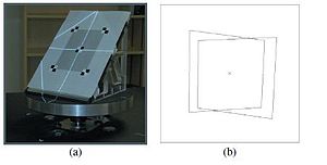
The anisotropic holographic diffuser and the mirror are mounted on a carbon fiber panel and connected to a 45 -degree aluminum inertia steering wheel. The steering wheel revolves in synchrony with respect to the images shown by the projector.
Synchronization in a system [ To edit ]
Since the frame rate at the exit of the graphics card of a PC is not always constant and cannot be adjusted on the fly, the video output of the PC is used as the main signal (master) for system synchronization. The high -speed projector also creates current table coding signals (frame). These synchronism control signals are sent directly to an intelligent motor system (eg Animatics SM3420D) that ensures that the movement speed of the mirror’s engine is kept synchronized with the signals sent from the projector.
As the mirror revolves up to 20 times per second, the persistence of vision creates the illusion of a floating object in the center of the mirror.
Projection of graphics on the screen [ To edit ]

In this section we will define how to make a 3D scene to show a correct perspective, using the provision of scanline or lightning layout.
We assume that the rotating mirror focuses on the origin and that its axis of rotation is the and vertical axis, with the video projector at point P above the mirror as in the upper figure. We also assume that the point of view we want to obtain at a height H and at a distance D of the Y axis. For the symmetry of rotation of our system, we can produce images of correct perspective for any display position in the circle defined by H , V and D, creating binocular images since H and D will be similar for both eyes. In practice, the set of perspective views that delimits V does not have to be a continuous circle, but can pass through a variety of monitoring positions at different distances and heights.
Double rotating mirror system [ To edit ]
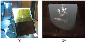
Thanks to this simple system we can generate color versions of our images. As can be seen in the image on the right we need to have a system of two tent -shaped mirrors.
On each side of the store, a color filter is placed between the diffuser of the holographic film and the first mirror of the surface, in this way we avoid introduction of specular reflexes.
Used filters are a cyan filter for one side and an orange filter for the other, in this way we get the approximate division of the visible spectrum uniformly in short and long wavelengths. RGB colors become an orange and cyan system and are projected.
To get the color, it is necessary to calibrate each plane of the mirro system independently. Then, the image is made in two parts, one for the side of the orange filter and another for the cyan filter side, thus the calibration process ensures that each side is rendered for all points of view. The effect for the viewer is similar to the color Kinemacolor system 2 and the choice of filters allows color reproduction for use in many scenes.
Apart from achieving the color, the double mirror system doubles the number of images per second that are shown to the spectators, allowing the sequential speed of the frames to be much more stable than in the monochrome system.
Applications [ To edit ]
• Maeda system [Maeda, 2003]: It is based on a system of a rotating LCD monitor. The Massa of this monitor limits the update rate, allowing only five revolutions per second, getting only five independent views.
• Sistema Transpost [OTSUKA, 2006]: Make 24 images throughout the outer edge of the projected video and reflect these images on an anisotropic screen of rapid rotation using a circle created by different faces of mirrors.
• 3D videoconference [California, 2009]: It is based on a structure composed of two mirrors in which the images are reflected and create different perspectives around their 360 degrees.
Articles and books [ To edit ]
•TRAVIS, A. R. L. 1997. The display of three-dimensional video images.
•ENDO, T., KAJIKI, Y., HONDA, T., AND SATO, M. 2000. Cylindrical 3D video display observable from all directions.
•DODGSON, N. A. 2005. Autostereoscopic 3D displays.
•MCDOWALL, I., AND BOLAS, M. 2005. Display, sensing, and control applications for digital micromirror displays.
•FAVALORA, G. E. 2005. Volumetric 3D displays and application infrastructure.
•OTSUKA, R., HOSHINO, T., AND HORRY, Y. 2006. Transpost: A novel approach to the display and transmission of 360 degreesviewable 3D solid images.
•AGOCS, T., BALOGH, T., FORGACS, T., BETTIO, F., GOBBETTI, E., ZANETTI, G., AND BOUVIER, E. 2006. A large scale interactive holographic display.
Links of interest [ To edit ]
Recent Comments