Map of staff-Wikipedia


The staff card is a general map of France produced, in its first version, at XIX It is century.
A royal ordinance of 1827 entrusted its execution to the deposit of the war even if the first tests took place in 1818.
The term Staff is used with reference to the staff officers who made the lifting. This card can be seen as a successful card of Cassini whose lack of update became more and more embarrassing (meanwhile the road network, the towns, towns and villages had progressed, as well as deforestation, the wooded surface even reached its historic minimum around this time) [ first ] .

The projection used at the design of the card is that known as good. The triangulation on which the planimetric lifting is based is that of geographers.
The lifting were made at 1/40,000, but the minutes remained handwritten; They were accompanied by a layer of the level curves, with an average equidistance of 20 m (40 m in the plain, 10 m in the mountains), drawn using rudimentary measures, intended only to guide the engravers in the figuration of the relief by hatching. Ploted in the direction of the slope, the hatching strengthens the visual rendering, the apprehension of the forms becoming more intuitive. Even if the rational figuration of the relief remains the great novelty compared to the Cassini card [ 2 ] , the fact remains that, despite the presence of points listed on the map, one cannot give the exact altitude of any point of the final document.
The forms of the frame are made with precision, in a comparable way to a contemporary IGN map.
The 1/80,000 card was not completely published until 1875 for continental France, in 1878 for the county of Nice, and in 1880 for Corsica. 56 years of topographic surveys carried out using “teclymeters” throughout the territory were therefore necessary to the completion of this card, planned from a triangulation of France carried out from the Paris Meridian [ 2 ] .
Before the engraving stage, the first form making this colossal work was a pressure drawing made by several contributors, all respecting the graphic standards of representation.
It is made up of 273 monochrome rectangular cuts on a 1/80,000 scale engraved on copper. By extension we commonly name these “staff card” sheets.
-

1866 staff map, 1/40,000 scale, Haute-Savoie department, near Chamonix, in very high resolution.
-
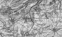
In the Plaine region (surroundings of Crèvecœur -le -Grand (Oise) -Montdidier sheet (Somme) –
1/80,000 – Revision of 1885). -
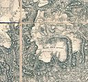
Extracts from the staff card
Projection [ modifier | Modifier and code ]

The projection on which the staff card is built is the projection known as good. This is based on the triangulation of geographers engineers with the Plessis ellipsoid ellipsoid as a reference ellipsoid 1817.
The projection of good is equivalent since it retains the surfaces (the meridians have for images not lines but competing curves). The projection center is made up of the intersection of the Paris meridian (Origin longitude) with the 45 It is North parallel (standard parallel); The point thus defined is in the town of Ayrens in Cantal.
Dressing [ modifier | Modifier and code ]
Cartery is carried out every 0.10 grade for meridians and parallels. The frame specifies the value of these lines in decimal grades (example: 50 ‘= 0.5 g ) Inner side and in sexagesimal degrees on the outside side (example: 50 ‘= 5/60 = 0.833 ° )
The choice of hatching as the only way to account ” in fine “Orography was clarified in 1827. This is the first time that we have been trying to rigorously represent the relief throughout the national territory. Cassini’s map, the primary objective of which remains referencing and rigorous positioning of all fires of France, only means to the reader a representation of the spirit of the relief, for lack of leveling measures. Because all the geodesic points used to establish the canvas of the “new map of France” have been calculated not only in planimetry but also in altimetry, on the side points appear on the map.
Difficult choices [ modifier | Modifier and code ]
The staff card succeeds the plan-relief.
The Mark the beginning of a great cartographic adventure in France. This is the date of deployment of geographers to start the “new topographic map of France [ 3 ] ». At the time, the majority of the workforce was assigned to geodesy work. For lifting, only eight topographers start their work in the Paris region at the 1/10,000 scale by having previously densified the existing triangulation network.
Given the concerns of the time and the innovative side of this operation, the officers who proceed to the raises then enjoy a certain autonomy in their work. For the representation of the relief, they place the level curves on the minutes to which they add hatching traced with the pen. These hatching does not respond to any strict rule and the officers then draw them without any particular constraint. Sometimes the Cohabitation Haches/Level curves produces an unlisy effect; It can happen in places that hatching is interrupted to let a level curve pass!
The first years of 1820 will see the completion of the minutes of the first sheets of the new card [ 4 ] . This first wave of production is an opportunity for the Topography Commission for the War Deposit to specify the lifting methods, which it appears urgent to do if you want the card bill to keep its uniformity.
In 1823, the topography commission with the powerful lieutenant-colonel, issued an instruction intended to clarify the methods of lifting in particular with regard to the question of relief. This instruction shows three techniques used until then in the establishment of minutes; For the minutes at 1/10,000 cohabit:
- a sowing of listed points;
- equidistant level curves of 5 m ;
- Hachings.
Following this inventory, the investigation continues on the probable passage of the 1/40,000 minute scale (clarified in 1824) and therefore recommends the pure and simple abandonment of the level curves. Indeed, the transition to 1/40,000 surveys involves bringing to 20 m The equidistance of these curves (against 5 m In the 1/10,000) for questions of readability of the card which, let us remember, is a reduction in minutes.
“In this interval we could often omit complete movements of land, or important accidents that characterize the figure of the soil, or if we wanted to keep them from 5 in 5 meters, as for the 1/10,000, it would be necessary Resolve to make a delicate miniature and of too difficult execution. »»
For the establishment of minutes on 1/40,000, the instruction recommends the use of listed points (“level ratings”) with the implementation of hatching (“drawn lines of larger slopes”). It specifies for the nature of the points listed: “The engineer will have to determine these level ratings on the culminating points, in the funds, on the edges and the sources of running and stationary waters, at the crossroads of the roads, at the bottom and at the top of the coasts on the same roads, And wherever they may be necessary for the greatest intelligence of ground movements and the inclination of various slopes. »» As for the implementation of hatching, in addition to their technical description, she advises the performer:
“It will be up to the engineer’s intelligence to choose the details that will have to be omitted or preserved. In some cases, he will omit the weak slopes which he will have to indicate in others, with the intention of keeping the whole and the spirit of the forms of the terrain. »»
Finally, the question of relief is closed by recalling the admitted objectives of the future card: “It is mainly on the edges of the big rivers, on the sides of the roads up to a quarter distance, that the figurative must be the most neat, in order to successfully serve military attack and defense operations . The level ratings, here and there on the banks of rivers or on the heights which are around them and dominate them, are especially necessary to indicate how and of how the banks are commanded, because the drawing always leaves uncertainty in this respect . »»
The investigation of 1823 came while reports report a dangerous heterogeneity of the work of the officers. Some represent the “vision” curves while others go so far as to take azimut measurements of larger slopes in order to draw these curves with the most precision it is given to them. The years which will follow 1823 will see a divergence of opinions on the question of the representation of the orography between the members of the staff of the war deposit, some judging the provisions of 1823 not satisfactory. In 1826, while for two years every minute has been lifted at 1/40,000 [ 5 ] , the Minister of War created on the proposal of General Guilleminot, director of the war deposit, a commission responsible for closing this question once and for all.
The first meeting of the renewed topography commission takes place the . The objectives speak for themselves: the time is for the standardization of the work and the cessation of the troubles:
“Coping the divergence of opinions and actions existing for too long between the various public services, on how to express the relief of the field in the drawing of special plans and topographic maps, as also on the hatch system and shadows of which it is most suitable to use ” , “To examine, among the different systems followed or proposed, which one must be generally adopted. »» , “To seek at the same time if it is applicable to all scales, and particularly to those of 1/40,000 and 1/80,000, the first employee for the minutes of the map of France, and the second for engraving . »» , also the cost aspect is not forgotten: “To ensure whether the system that will be prescribed in this regard will not lead to much more considerable expenses than those that have been planned. »»
In addition to those already used, an unprecedented technique is offered to the Commission. This is the “horizontal hatching process” which is based on the establishment of a multitude of levels of levels of the same thickness with a low equidistence so that they form shades. Presented as faster to implement than hatching This method is to be compared to zenithal lighting shade.
For the card establishment below 1/5,000, the commission is unanimous: it is the use of levels of levels that prevail [ 6 ] .
Regarding the card of the staff, the Commission has several models of the same area draw up to give itself the means to decide.
It was not until March 1827 that decisions were made. Several visions are confronted:
| Minutes at 1/40,000 | Minutes at 1/80,000 | |
|---|---|---|
| Geographers | Curves | Hachures |
| General Brossier based on the opinions of the powerful lieutenant-colonel and Colonel Jacotin | Curves + shade | |
| General Lachasse de Vérigny, General Brossier | Curves | Hachures |
| Commandant Lapie | Hachures | |
| Fleury genius general (lifting experiences in Catalonia) |
Curves | |
The table above sums up the opinions developed before the Commission. Some want a rigorous representation of the relief while others favor the artistic effect alone. The majority agree to combine the two visions without deciding on the methods to be used. After harsh discussions (each method has its advantages and disadvantages), the commission nevertheless gives an opinion:
For minutes; It approves the use of level curves, the equidistance of which should be respected on the whole of the same card.
For the net before engraving; Hachings will be added to the level curves.
Now we add to the minutes a layer separate from the level curves [ 7 ] whose equidistence adopted responds to the rule which consists in dividing the denominator of the ladder of the card to be raised by 4,000. For the map of the General Staff 80000/4000 = 20 m . However, since the intensity of the relief of an entire country is not uniform, adaptations of this value occur in the very mountainous or very low relief regions.
Each geographer engineer gives these layers to the deposit and it is only after the curved level → hatching transformation takes place. From now on, the execution of hatching is “centralized” in Paris. This decision allows better control of the implementation of hatching by reducing the differences of interpretation encountered until then. THE , order is given to officers of “S’abstenir de Tracer Les hashures” And to devote yourself only to the 5 -meter equidistance level curves traced in pale China ink. For areas with high relief, it is recommended to double the equidistence; Similarly, the possibility of reducing it locally is admitted provided that the inter -lap curves are more finely traced. This order also specifies that the officers will have to work to set up “shades washed with a brush” in order to strengthen the evocation of the relief by the curves. Still in prevention of differences of appreciation, standard shades are communicated to them. Finally, it is specified that the leveling ratings determined on the ground will be worn on the minutes in black while the dimensions of the main curves will be worn in red. However, as in all reforms, old practices have a hard life and the following year, circulars were issued for section leaders so that the officers whose responsibility they have respect the “rules of the art” to which They have the obligation to comply.
In 1830, twelve years after the first surveys, problems still persisted. Through notes, questions are formed. We wonder for example about the merits of maintaining 1/20,000 surveys [ 8 ] While the production scale (the 1/80,000) does not keep all the details. A reflection relates to the location of the side points that must, you think, be mainly on the characteristic lines of the terrain.
The , an original order of General Pelet [ 9 ] is given to the commission responsible for receiving the work of the officers. It is a question of establishing a classification by “order of merit” of the twelve best ratings. In addition, it will have to provide the Director of War a report on geodesic and cartographic operations corresponding to the lifting. The following year, the , an order will merge this commission with that of engraving to form the commission of graphic works.
In the merger order, Pelet provides an appreciation that it is important to note as it reflects the concerns of the service at the time. “The publications […] of the map of France must undergo from us the most rigorous examination and a complete revision before the moment when they will be delivered to the observations and the attacks of criticism and, I say it with deep pain , she had the opportunity to practice more than once. »» . The general will go further by putting in place which is similar to a real “quality control” with in parallel the creation of a competition: “It is not enough to reach perfection in all our graphic work, it must be maintained and increased it; We must create emulation among those who are called to help us, so that, designers and engravers, all those who want to deserve the beautiful artist name do not remain outside the progress we want to obtain. I think it would be useful to establish a competition among them and to give a reward to the one who, in drawing or engraving, would have produced the best work. »» before concluding “The purpose of what I propose is easy to grasp: I want to improve and improve the work of which we all share honor and responsibility, although it weighs more particularly on me. I especially want to sit on solid foundations the execution of the great work entrusted to us, and at the same time involve it in general progress. »» .
The competition mentioned is to give one out of 20 note to the work of geodesians and topographers who was the weighted average of four notes:
- One note on 20 coefficient 3 for the line.
- One note on 20 coefficient 4 for the drawing of the line
- one note on 20 coefficient 2 for shades
- one note on 20 coefficient 5 for “The accuracy and intelligence of soil movements”
This competition shows once again, by the importance of the coefficient has been awarded, the concern for the question of relief.
One of the powers of the commission is to ensure the good connection of the sheets to be engraved. Among other things, she will have to have 1/80,000 reductions of the sheets to engrave to engrave “Note the general effect of ground movements and the accuracy of connections” .
The Commission regularly published recommendations for section chiefs and topographers. Once again, the emphasis is on orography. Some new features appeared from 1839: from now on, the officers will take on field models with them to help the installation of the curves. Soon generalized, “curves” appearances appear on certain surveys and allow to dissociate the modeling of the land of planimetry. Details are provided as to the choice of on the points. They must be along all the land storage but also in terms of depression. A methodology is even specified:
“[…] Before exploring a country, it is appropriate to penetrate its hydrographic configuration. We get there by tracing on a large -scale map the lines of water sharing or the ridges of the hydrographic basins, even in their smallest subdivisions. We then make the successive dependence of these parts familiar and we discover the constant relationships or analogies which serve as a sort of compass to light up the march and shorten investigations. ».
The concepts of “water sharing line”, “ridge line”, “passes”, “seed” are discussed and specified. It is a question of “expressing on the cards all the lines of the peaks which, with the main physical circumstances, contribute to determining the complete skeleton of the land. ». It is specified the importance of placing dimensions on four types of line which are:
- Water sharing lines.
- Talweg lines (“Thalweg”).
- The lines of larger slopes and the horizontal curves which correspond to the passes and the other characteristic points.
- THE “Lines of separation of the banks with the plateaus and the lower plains”.
The attention of the performers is paid to the complementarity between this network and the hydrographic network whose study forms what is then called “the theory of the field” which will later become, with geomorphology, a science in its own right.
Despite these indications, this methodology remains very vague in the eyes of the officers. The little training they had on this subject allowed them to represent the relief in a very meticulous, but not very expressive way on the actually characteristic features of the area they had to raise.
The A general instruction is transmitted to all the topographers of the map of France; Even if it was completed later, it will be the last. It consists of a confirmation of the various measures taken in the previous instructions and tries to elucidate the last points that are problematic. This is a reference text that will continue until the card completion.
This instruction informs us about the magnitude of the task that could be assigned to a staff officer. In “ordinary countries”, the area to be raised extended to a square of 20 km next to ; In the middle mountain the side was reduced to 17 km (16 km in the high mountains) while in “roughly flat countries” the side could reach 25 km . Part of the instruction is devoted to the positioning of the side points. She recalls that it is necessary to prefer points judiciously chosen at more scattered and over-quantity points. The instruction recommends placing them along the characteristic lines of the relief mentioned above, but also in other remarkable places: in sources, in the confluents of the rivers as well as in the nodes of the main roads [ ten ] .
The investigation also specifies the conditions under which the altimetric determinations must be carried out: “We should avoid taking ratings of height at too long distances, especially in the morning very early and in the evening of sunset, because of the refraction. »» . It also reports on the difficulties of determination that officers could encounter and offers methods. It underlines the fact that the calculations of the dimensions must be carried out on the ground so that it can repeat the measures in the event of an error. The calculations are recorded in special notebooks where each point is clearly identified.
The formula for calculating on the side points is as follows:

With: DN the elevation sought after; K distance; D the zenithale distance; n refraction and r the average radius of the earth.
The author of this formula is none other than Pierre-Simon de Laplace. Commander Maissiat, head of the topographic section of the war deposit, calculated tables of this formula of which each officer had copy.
Still on the relief register, another part of the investigation deals with level curves. It mentions the layout of the online dry valleys punctuated.
Also in 1851, the invention of the arithmometer made available for topographers facilitates the exploitation and calculations linked to the topographic statements [ 2 ] .
The early 1860s saw the execution of the last surveys. These are mainly territories ceded to France in 1860 (County of Savoy and Nice) as well as Corsica. These are mountainous areas. We may have to ask the question of the quality of orography, especially in these areas which, at the time, represented little interests. In 1863, when the last lifting in Savoy was coming to an end, Lieutenant-Colonel Borson wrote on this subject:
“The officers must be warned against relaxation which can win them easily, in front of the ungrateful task of having to raise ice deserts or sterile and uninhabited areas. The point of view to be placed here is that of the new requirements of science, which today makes these regions, still unknown half a century ago, the object of meticulous explorations. ». Borson, however, returns further to “deserts”. For glaciers, alpine areas and inaccessible ridges, he writes: “We will naturally try to determine the ridges by their striking points and fix the position of the thalwegs. The general forms of the terrain and the secondary accidents will then take shape more or less on sight, but we will take good care, in the most important stations to draw one or more profiles, which will serve to keep the lasting trace of the appearance of the premises , and which, united and coordinated with others, will make it possible to obtain a fairly precise figurative from the region. »» .
The Hache Technique [ modifier | Modifier and code ]
If level curves are based on altimetric considerations, hatching accounts for the slopes of the land and are therefore more intelligible for neophytes. However, hatching can only be implemented on the express knowledge of the level curves from which they draw all their rigor. When their layout is rigorous, one must without difficulty go from one type of representation of the relief to the other.
By definition, hatching is always normal with level curves. Their route always follows the shortest path that separates two consecutive levels.
The realization of hatching is based on compliance with three basic rules:
1) The principle of the greater slope line:
The line of a hatch always follows the largest slope line that is directly linked to the water flow line. This principle means that in all circumstances any hatch is perpendicular to the tangent of the level curve it intercepts.
2) Quarter law:
This law specifies that the spacing of the hatching is fixed in the quarter of their length (delimited by two level curves). Thus, the greater the slope, the shorter the hatching, the more tight they are. The rigorous respect for this rule makes it possible to find the layout of the level curves from hatching. The line density is thus directly linked to the intensity of the slope.
There are derogations from this rule: when the slopes are very strong (medium with pronounced relief) The drawing of hatching becomes impossible (spacing between extremely reduced hatches), the following directives are then adopted:
- The minimum spacing between hatching is fixed at half a millimeter, which corresponds to a spacing between level curves of 2 millimeters (0.5 mm x 4 = 2 mm );
- The thickness of the hatching is increased for the strongest slopes so as to obtain a shade proportional to the slope;
- The hatching gives way to the sign of the escarpment when the spacing of the level curves does not exceed a quarter of a millimeter (which corresponds to the 1/80,000 with an equidistence of 20 meters to a slope of 1/1) .
3) use of a tuning fork:

The law of the quarter regulating the questions of the spacing and the length of the hatching, remains to be called their thickness.
A diapason allows the executor to have a typical hatch model at any time, designed so that the intensity of the shade is proportional to the slope.
Regarding the map of the General Staff, the representation of “the mountain” in the first minutes was only limited to compliance with the quarter rule. Later, the principle of “magnification” was involved before the adoption of Colonel Bonne’s first tuning for.
This tuning fork was fully appropriate to the average slopes but had the drawback of a very contrasting rendering between the plains of plains (almost inexpressive) and the mountainous areas (heaviness of reading due to the “invasion” of the hatching).
After multiple modifications, it is ultimately a so -called “French tuning for” tune “developed by Colonel Hossard who succeeds that of good. It has a scale of twelve colors associated with type slopes ranging from 1/1 to 1/144 ° [ 11 ] . It is established so that the HACHURE ratio over intervals equal once and a half the slope. In order to help the executor, the spacing of the level curves corresponding to each shade is on the tuning fork.
Even if most of the map of France is engraved by following this tuning for it, the fact remains that a possibility of interpretation persists. Colonel Hossard writes on this subject:
“All the tests tempted to express the speed of the slopes, due to the intensity of the colors, have helped to prove how difficult it is, with a single tinition of hatching to keep a sufficient model for the plains and the medium regions, Without reaching the dark almost absolute when we approach the high mountains. In the new tuning fork, we proposed to properly distribute the tones, from the softest slopes that can be expressed to the strongest inclinations … However, if such a tuning for it was followed in all its rigor, we would only get a card without expression in all its parts; It is therefore of course that the tuning for a purpose is to ensure uniformity in the work, without completely excluding the artistic part of the drawing, which must help powerfully give it expression. The designer must take the tuning for type in all the intermediate slopes between the softest and the steepest of the region whose figurative he performs by reserving the ability to soften the platforms a little and give more expression to the Tilt maximum of the slopes and in particular the banks of the valleys. »»
The strict respect for the three basic rules allows, as we have seen, to trace the hatching without any hesitation in the case of linear tracks. Because this hypothesis is far from responding to the subtleties of a real relief, the designer must always handle tunes by adapting them to the various situations encountered so that the treatment of a hatching relief undoubtedly calls for more reflections than the Plot of simple curves.
Towards a leveling network [ modifier | Modifier and code ]
One of the major “new” novelties brought by the staff card is the attempt to represent a reasoned representation of the relief. To do this, even before the topographic lifting it was necessary to put in place a whole sowing of points calculated at altitude distributed in a judicious manner in the area of the map to lift.
Often, officers will have to set up these points starting from geodesic points from the triangulation of geographers. However, the instruction of 1851 mentions leveling work carried out by an administration other than the army:
“Bridges and road engineers will often be able to give officers the levels of large roads and the main rivers, which will be precious documents for them. These levels are usually reported to a higher benchmark; But by means of a good common rating, we will obtain the height of this plan, and by taking away from this height all the leveling dimensions, we will have the heights above the sea ” .
At the time, some large cities had a specific leveling network (that of Paris dates from XVII It is century). Very often these networks are not attached to a national reference. The administration of bridges and roads has also carried out linear leveling operations on the main communication axes (roads, rivers, etc.).
More than before, the second half of the XIX It is Century is going, with the pre -industrial era, see the start of the national communication routes (railways essentially but still canals, roads, bridges, etc.). For this large -scale work, engineers need to carry out levels over several tens of kilometers. Departmental networks are emerging but very quickly the need for a network of points known in the same altitude system is felt; From there to what the General Stream card does not include them, there is only one step!
Paul-Adrien Bourdalouë (1798-1868), engineer of bridges and roads, was entrusted with different local works from the 1830s. For almost twenty years he will improve operating methods [ twelfth ] (invention of new tools, shortening of the aims, etc.). In the 1850s, many departments had their leveling networks but there is no coherence between the networks of two adjoining departments. This is problematic for certain major sites.
In 1857, Bourdalouë was entrusted with the realization of a general leveling of France. Two operations are distinguished: a leveling of high precision (baselines constituting the national framework) and another of details which are then called “general leveling of the departments”.
The realization of this network will range from 1857 to 1864 by the establishment of 15,000 cast iron benchmarks throughout the national territory. As early as 1859, the work was sufficiently advanced so that the Mediterranean Sea was seen is a few centimeters higher than the Atlantic Ocean. THE , a ministerial decision fixes the zero leveling at line 0.40 m From the tide scale of Fort Saint-Jean de Marseille.
In 1878, the Ministry of Public Works entrusted Charles Lallemand (1857-1938) the task of improving and densifying the Bourdalouë network. To do this, he was appointed director of a service created in 1884: the general level of France (N.G.F.).
Observation of the level of the seas, by the installation of a tide marsh in Marseille of the At , makes it possible to fix a new fundamental point which “descends” from 71 mm “Zero Bourdaloue”. The “zero lallemand” thus defined is always the reference of national leveling.
From the middle of XIX It is century, adapted maps of the staff card was emerging. Even if “the cartographic offer” tends to expand, the reference card remains the staff card until the end of the first half of the XX It is century. Most often it is a change of scale for specific uses:
Type 1889 [ modifier | Modifier and code ]

In 1889 economic considerations led the decision to split the leaves into four quarters (numbering from north to south and west to east). Updating a board previously required the use of a engraver for a whole sheet; Now four different engravers work on each quarter from which a productivity gain. This decision brings the number of cuts from 273 to 1,092 cuts.
Generally the date of the card is at the bottom right. For example the inscription “3024” means ” ». You can also read the name of the engraver and the price of the card.
Discounts [ modifier | Modifier and code ]

- 1/100,000 reduction and colorization in 5 colors: Map of the vicinal service or known as the Ministry of the Interior;
- 1/200,000 reduction in 81 sheets. 2 types (in 6 colors) have emerged: type 1880 and 1912;
- 1/320,000 reduction in 33 monochrome sheets;
- 1/500,000 reduction in 15 sheets (in 5 colors): “Care card”;
- 1/600,000 reduction in 6 sheets. Color and monochrome versions coexist.
Enlargements [ modifier | Modifier and code ]
In 1898 there was a major evolution in the production of the staff card:
- Change of scale: from 1/80,000 to 1/50,000. The 1/50,000 scale had been retained during the first reflections on the map.
- Change of projection: The projection of good is abandoned in favor of the Lambert projection from the brand new French geodetic system NTF.
Given the extent of the change, the operation comes at the time of an update of an existing sheet.
There are four types of this “new generation” staff card:
- Type 1900: The cards are colored with 8 to 12 colors;
- Military type (known as “type M”) 1922: 3 colors;
- Type in 1922: 5 -colored colorization and replacement of hatching with level curves.
- Type 1972: Colorization in 5 colors and minor modifications of symbolization [ 13 ] .
During the First World War, a series of cards having to satisfy the shooting master plan was produced by photographic increase [ 14 ] by the army geographic service. The scales used are 1/20,000, 1/10,000 and even 1/5,000. On these maps, there are enemy organizations: trenches, batteries … A color code is adopted: blue: enemy installations; Red: Friendly installations; Everything else is black. 274 Dimension sheets 64 cm for 40 cm are thus produced.
The IGN via its geoportail today offers in 2D and 3D a rebuilt metropolitan map (digital assembly) from the 78 original drawings of the staff card, drawn 1: 40,000, Watercolors, recently scanned (with a resolution of 40 microns) then georeferenced by the IGN. The projection has been modified, going from that of Good to projection Lambert-93 allowing this card to be superimposed on modern cards. The card is available in “Slabs” 20 × 20 km .
The posterity of the staff card of XIX It is century was a new topographic map of France produced in XX It is century by IGN, and only completed in 1980 [ 2 ] .
- IGN 2019 [ ‘ Ancient forests; Inventory of forests already present in the first half of XIXecentury » ( Archive.org • Wikiwix • Archive.is • Google • What to do ?) ] ; Periodic synthesis of the forest inventory, If, n O 42, July 2018 see p 6 of the [ ‘ Download IF n o42, PDF de 7,9 MO Version PDF » ( Archive.org • Wikiwix • Archive.is • Google • What to do ?) ]
- Quote or explanation given in the documentary The cartography of the staff , Below the cards presented by Jean-Christophe Victor, indicated in external links .
- This date appears in a circular addressed to all the prefects issued in early 1818. It was signed by the Minister of War at the time: Marshal-Comte Laurent de Gouvion-Saint-Cyr
- Paris leaf: 1820; Beauvais leaf: 1823; Melun leaf: 1824
- Since an order of February 25, 1824
- Colonel Bonne is totally against the idea of calling on curves of levels, on any scale whatsoever. He recalls that their use implies a perfect and meticulous knowledge of the relief.
- This technique began to be used in 1737 by the geographer Buache, but the aim was then only an approximate representation of the relief without any precise indication of the leveling.
- The liftings carried out entirely on 1/20,000 concerned the “sensitive” area in northern Alsace and Lorraine. The “stamp” area that constitutes the Paris basin was lifted at 1/40,000 with 1/20,000 fragments. All the rest of the territory will be lifted exclusively on 1/40,000.
- Baron Pelet, lieutenant general, peer of France, director of the general deposit of the war from 1830 to 1850.
- This provision is found in current IGN maps at 25,000
- In practice, the longest hatching that we meet by consulting the different sheets of the card do not exceed 16 mm, proof that the engravers were limited to representing the slopes greater than 1/64. Indeed the length of the hatching, can go, depending on the French tuning for 34 mm (1/144).
- Bourdalouë was responsible for the leveling necessary for the drill of the Suez Canal by Ferdinand de Lesseps. Burned in Bourges (city of which he comes from), his grave has the shape of an Egyptian pyramid and is fitted with a leveling benchmark (landmark g’.a.k3-75a altitude 147.391 m)!
- The latter type, for lack of being mentioned on the cards, is less known than the previous ones, a fortiori when it only makes minor modifications to the type 1922 (difference in trating colors and the thickness of the lines). He is documented in the brochure Basic geographic equipment specifications of the national territory / Paris: National Geographic Institute, 1972
- This enlargement process only increases the defects in the card (error in positioning objects for example).
Bibliography [ modifier | Modifier and code ]
- Heny Marie August Berthable, The map of France, 1750-1898, historical study , 2 volumes, Paris, Imprimerie du service geographique, 1898-1899.
- Pierre Colombé « The so-called “staff card” card at 1/80,000. Work in Périgord », Bulletin of the Historical and Archaeological Society of Périgord , t. 114, n O 2, , p. 135-143 ( read online )
- Notice to be used for the study and execution of leveling on the map of France at 80,000, A. Maurel
- Marcel Huguenin, History of the cartography of the new map of France , Paris, printing of the National Geographic Institute, 1948.
Related articles [ modifier | Modifier and code ]
external links [ modifier | Modifier and code ]
Recent Comments