Frequency converter – Wikipedia
A frequency converter is a converter that creates a different AC voltage from the feeding AC voltage.
The output frequency and output amplitude can usually be changed. In contrast to “simple” convertible, the devices usually serve to supply three-phase asynchronous engines, since they set the frequency and amplitude of the output change voltage using sensor technology according to the applications of the motor and its current load. So -called servo converters also have inputs for the angle position of the rotor and can be used as a positioning drive.
Depending on the design, frequency converters can be fed with single -phase change voltage, three -phase change voltage or DC voltage and resulting in a three -phase change voltage for the supply of three -phase motors.
Circulars are electrically structured, but do not serve to control and supply an electrical engine, but usually work with a fixed frequency and voltage amplitude at the output for supplying several different consumers.
Frequency conversions and converter are electronic devices without mechanically moving components. In contrast, a converter is a rotating electrical machine that is used in railway power plants, among other things.


In principle, the indirect, static frequency converter consists of a rectifier that feeds a DC voltage intermediate circle, and an inverter fed from this interim circuit. The intermediate circuit consists of a capacitor to smooth the DC voltage and inductance for interference. Both uncontrolled and controlled bridges are used as a rectifier. When using a controlled bridge, the intermediate circuit can also be feeded with an active performance factor correction (PFC).
Several inverters can be connected to the intermediate circuit, so this type of frequency converter is very often found in machine tools. An intermediate circuit can also be realized with DC and a smoothing throttle as a storage element. The storage element in the intermediate circuit, the capacitor in the case of a DC voltage circuit and the smoothing throttle in the event of direct current, bridges the gaps in the energy supply.
There are also direct converters, also referred to as a matrix converter, which can do without any intermediate circuit. Matrix conversions require a complete energy supply, usually these converters are designed for three -phase change current.
The inverter works with power electronic switches (controlled bridges). Among other things, this can be performance transistors, such as
It creates a variable tension through pulse duration modulation (PDM). The amount of the resulting output voltage and also their frequency can be regulated within large limits. In addition to the pulse duration modulation, there is also sinus frequency converters with self -oscillating variable clock frequency, which create a purely sinus -shaped tension at the output.
In order to be able to brake, simple frequency converters have a so-called brake chopper, which leads the excess energy from the intermediate circuit into a brake resistance and converts it into heat. Otherwise, the intermediate circuit voltage would increase and destroy the capacitors. The chopper (interruption) becomes a pulse duration-controlled to the Quasianalogen regulation of the heating output.
For brake performance from 1 kW – the limit is fluid – more complex back -feed frequency converters are used. The advantage is, financially, less in reducing energy costs, but in the saving of the braking resistance and its cooling. Its input circuit in front of the intermediate circuit is very similar to the output circuit, only the frequency specification takes place on the net and with a blind power minimization.
A direct rash with thyristors can only generate output frequencies less than the input frequency. Intermediate circuit conversation and direct converter with IGBTS, on the other hand, can also generate output frequencies that are above the input frequency (up to several hundred Hertz).
Directly converters are always fed back. Another advantage of direct intermediate is that this same Working and output frequency in a practically loss-free work without switching processes (bridge operation). Therefore, these are particularly suitable as a heavy or gentle circuit for otherwise even running drives (e.g. elevators).


If asynchronous engines are operated directly on the AC voltage network, you have a fixed speed dependent on your pole pair number and the network frequency, the nominal speed. When they start, high power peaks are created and the torque is low. This is counteracted conventionally by different means. This includes star triangle gearshift, event transformer and Thyristor-Anlasser with phase-cutting control. In this way, however, no higher torque can be achieved below the nominal speed, and operation above the nominal speed is also not possible.
Extended speed range [ Edit | Edit the source text ]
In contrast, frequency converters make it possible to gradually achieve speeds of almost zero to the nominal speed without the torque sinking (basic parking area). The engine can also be operated via nominal heat frequency (field weakness area), then the cast cast drops, however, since the operating voltage cannot be adapted further to the increased frequency (see U/F operation). Due to these properties, frequency converters are widespread in industry and allow the use of inexpensive standard asynchronous engines in an expanded speed range.
For engines with a type shield indication of your conductor voltage of δ/y: 230 V/400 V, the basic area area can be set to a 400 V converge up to 87 Hz
( 50 H With ⋅ 3 ) {displaystyle (50,mathrm {Hz} cdot {sqrt {3}})}And thereby operated at a higher speed for nominal torque if it is connected in a triangular circuit. (This also applies accordingly to other network voltages.) However, it should be observed, among other things, that the own fan represents a higher load and the iron losses (depending on frequency) increase so that the engine can be overloaded thermally or mechanically.


For the smallest lower speed (or lower limit frequency), the slip speed (= synchronous speed minus asynchronous speed in the design moment) and the pole number of the electrical machine is decisive. The slip frequency
( f S L ) {displaystyle (f_{SL})}In the rotor, the relationship is calculated: slip speed
( n S L ) {displaystyle (n_{SL})}

Pole number
( p ) {displaystyle (p)}

shared by 60:
f S L = ( nSL⋅p60) {displaystyle f_{SL}=left({tfrac {n_{SL}cdot p}{60}}right)}

.


The slip frequency must be exceeded for safe operation (rule of thumb: double slip frequency for a suitable lowest speed), otherwise the engine will block at a standstill. This restriction is avoided in modern formers through active slip compensation.
Starting with high torque [ Edit | Edit the source text ]
By programming a frequency ramp to start, difficult start -up conditions can also be mastered without strong overcurrent tips.
With a descending frequency ramp, braking is also possible. Many frequency converters can monitor whether the engine still runs within a permissible slip and thus a Tear off prevent the rotary field. Circulars with room pointer modulation (Space Vector Control) enable the separate regulation of torque and speed for an asynchronous engine, in which the actual frequency is followed by the registered repercussions of the motor.
Frequency converters are used in particular on three-phase motors to improve or expand their start-up and speed behavior. Frequency converters are now also available for one- or two-phase alternating electricity motors such as B. capacitor motors to regulate them at the speed. The frequency converter, if necessary, takes over the provision of the second phase generated by the capacitor.
There are also single -phase frequency conversions in which no changes can be made on the single -phase engine with a capacitor. [first] This is particularly interesting for existing drives such as pumps, fans, table drilling machines or drives for transport tapes. With restrictions, gap polar engines can also be operated on such frequency converters. The devices initially raise the capacitor motor with nominal frequency and then reduce the frequency according to the desired speed. This is necessary because the capacitor can only generate the auxiliary phase required at the start. Because of this, such frequency converters cannot increase the starting moment.
Frequency converters generate strong electrical interference signals on the engine supply line, which can not only interfere with other consumers, but also lead to increased insulating pollution in the engine. The engine supply line must often be shielded to avoid interference. A so -called sinus filter can also remedy between the converter and the engine. Such sinus filters differ from a network filter by their lower cut -off frequency and higher resilience.
For these reasons, frequency converters require a professional installation.
When operating above the nominal speed, increased vertebral current and hysteresis losses occur in the engine, which is often compensated for by its faster rotating fan wheel. The engine must be approved for the frequency for continuous operation. Slow rotating motors up to 3 Hz, as is often used in industry, are cooled by foreign fans, the speed of which depends on a so -called external network, i.e. three -phase current of 50 or 60 Hz.
Frequency converters with output frequencies over 600 Hz are suitable for controlling centrifuges for uranium enrichment and are therefore subject to dual-use export restrictions. Most German manufacturers have reacted by either offering products (partly clearly) under this limit frequency or offering their products for larger frequencies with special firmware. Such requirements are also rare; You can sometimes find them with extremely high -speed milling engines and in turbopumps. Devices with a lower limit frequency are not subject to any restrictions. Servo converter as a special case is actually not intended for certain fixed rotary field frequencies, but can be operated very easily. They therefore represent an borderline case (approximately like a civilian bus, which can also be used as a troop van even without additional effort …).
In frequency converters, a distinction is made between several main areas of application, which also decide which type, i.e. with which characteristics, is used:
Electrical lanes [ Edit | Edit the source text ]
Frequency converters are called on modern electrical lanes Traction organizer To generate the three-phase current for the continuously adjustable three-phase drive motors from the respective railway current system of the overhead line or the power rail.
The traction power judge typically consists of four -quadrant authors (4Qs), a intermediate circuit operated with DC voltage (ZK), pulse inverter (PWR) and in direct current networks, if necessary, a brake device (BST). When operating under a DC voltage network, the 4Qs can be dispensed with.
Pump and fan applications [ Edit | Edit the source text ]
At the beginning (from 0 Hz), almost no torque is required here, since the air resistance is at the beginning of 0. However, the torque increases approximately square. The design speed corresponds to the design torque.
The drive torque drops square at the speed, so that the necessary drive moment drops to 25%when the volume flow is halved. Since the mechanical drive power is calculated to M × 2 π × n, the drive power is now only a eighth of the nominal output. (M ⇔ torque, n ⇔ revolutions per second) Any losses of the converter are not taken into account.
Lifting and locomotion applications [ Edit | Edit the source text ]
At the beginning (from 0 Hz), a high lettling moment is required, which exceeds the design moment far (depending on the application, approx. 125–200%). Since the rotor of the engine turns evenly or accelerates evenly, the required torque remains constant. This torque usually moves a little below the torque characteristic of the engine.
A soft start of the system can also be realized via the converter.
Servo drives [ Edit | Edit the source text ]
A servo drive is an electronically controlled drive with location, speed or torque control (or a combination of the same) for applications in production machines and automation solutions with high to very high demands on the dynamics, the areas and/or the accuracy of the movement. Servo drives are often used in machine tools, printing presses, packaging machines or industrial robots.
Their use is characterized by the fact that they can often be operated with strong speed and torque changes and briefly with high overload. Servomotors can usually provide their nominal torque at a standstill for a long time as a holding moment. An exceptional case can be vertical axes, here a synchronized shutdown of the servo engine and the connection of a mechanical parking brake can also be useful. A general reduction in movement and holding forces can also be reduced by counterweights or feathers. The dimensioning of the drive of a vertical load may be significantly reduced, accordingly in operation, permanent energy costs. The standard example here is the ship’s lift: Always roughly the same, therefore easy to compensate for, the necessary drive power relatively low, drive shutdown and mechanical brake not only well possible, but very desirable.
Especially in the transportation of people, security aspects of any cost factors rightly gain the upper hand anyway. A security view is essential anyway, especially when the potential energy is stored. The most critical case is the failure of any energy supply, and it always has to be safe. So stop brakes must work without a power supply. Vertical axes may only be dependent on permanent energy supply if there is no danger in the event of a failure.
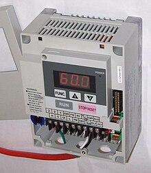
In addition to the performance connections, frequency converters usually have digital and/or analog inputs and outputs. At an analog input, e.g. B. a potentiometer to adjust the output frequency are connected.
For example, the unit signal level 0–10 V, 0–20 MA or 4–20 mA are used for analog control.
For most frequency converters, intersections for field buses or industrial Ethernet are also available. Examples of such interfaces are CAN with canopes or devicenet protocols, professional with professionalrive, interbus or the Ethernet solutions Ethernet/IP with CIP Motion, Profinet with Profidrive, Ethernet Powerlink, Ethercat or one of the three Sercos versions. Drive profiles have been defined so that these frequency conversions of the different manufacturers behave equally on these different fieldbuses. Four of these drive profiles have been determined in the international standard IEC 61800-7 worldwide.
By parameterization, converters can be adapted to the motor to be absorbed in order to optimally operate and protect it. In the early days, this often happened through potentiometers and dip switches. Potis as purely analogous and therefore difficult to reproduce setting elements are practically extinct, DIP switches are sometimes still used, especially for address settings. The next stage was specifically referred to as Keypads, which are firmly installed or on the converter and the navigation in a menu structure. PC software is now standard almost for all manufacturers; An online connection is made via a proprietary interface or one of the many industrial standards, which allows comfortable commissioning with display of current values, controls from the PC and also secured configurations.
Finished data records can be loaded into the converter via an interface or a data carrier. Keypads are still popular and widespread for this purpose as well as for quick diagnosis and parameter change.
Digital frequency and serial judges include enormous computing power. This has the following background: 2/4/8/16 kHz are common as the control clocks, whereby everything below 16 kHz results in tormenting noise loads in soft environments. The trend is towards the highest possible bars. Reciprok can be processed or standard acts of 500/250/125 or even 62.5 µs. Correspondingly powerful CPUs therefore still offer potential for additional features such as simple process sequences, but also for fully fluid soft PLS. You can use them (this sometimes happens for very simple applications with high cost pressure), but in general they are rather poorly accepted. The clear separation in controller, HMI and motion, also in the hardware, is still clearly preferred.
Many models can even measure the drive properties (often referred to as a autotune) and set their control parameters independently as part of the commissioning.


If the converter is able to transfer energy from the intermediate circuit to the engine and when braking, back into the intermediate circuit, one speaks of four quadrant operation.
Since the capacitor is loaded in the intermediate circuit in the brake or generator operation, overvoltage must be prevented if the input of the input is not comprehensible. Either the frequency converter reduces the brake torque or there is a brake cutter. This periodically switches a brake resistance to reduce the energy.
Returned converter can transfer the energy from the intermediate circuit back into the network by changing direction to a mains frequency.
All types of engines work with back -resistant converters with a decreasing speed or negative torque (brake operation) as a generator. This is particularly interesting for vehicles, drives of elevators and cranes and elevators. Locomotives can also resin the brake energy if the network allows it. See also useful braking. The rear -feeding in hybrid electro -mobile vehicles comes into either the battery or a double -layer capacitor.
In the case of wind turbines and in small hydropower plants, an inexpensive asynchronous generator (as well as an asynchronous engine) will often be used without the speed of the power frequency.
The DC intermediate circuit can also be connected to the intermediate circuit of one or more frequency converters to recruit energy recovery.
U/F operation [ Edit | Edit the source text ]


This is the simplest mode of operation of a frequency converter. The converter regulates the motor voltage and the frequency in a constant ratio. The frequency and voltage are kept proportional to each other up to the nominal frequency of the engine. This is necessary due to the inductive behavior of the engine and leads to a torque, which is over long areas, without overloading the engine.
At very low speeds, however, this operating mode leads to a lower torque due to the ohmic resistance of the winding. To fix this, a voltage increase (boost) can often be set in the lower frequency range (i × R compensation).
In the U/F operation, the speed of the connected engine varies depending on its load.
A constant speed return can either be achieved with a regulation using a speeder or using a slip compensation, which enables a constant speed without speed return. U/F operation is therefore only sufficient for low demands on the speed of speed and without a heavy start.
The above -mentioned characteristic line shows that the magnetic river is kept constant up to the nominal frequency of the engine. If a three-phase asynchronous engine is operated with a frequency converter over its nominal frequency, the engine is located in the field of weakness. At this point, the output voltage of the converter reaches its maximum value and the torque drops.
Field -oriented regulation [ Edit | Edit the source text ]
The vector control or field -oriented regulation consists of a speed controller based on a subsequent stream controller. The current blind and impact current components are regulated. The engine parameters are saved in an electronically stored engine model or, if necessary, even determined and adapted automatically. This has the advantage that there is no separate speed measurement and recovery in order to regulate the speed and moment.
The reduced size used for regulation is the current current. Based on the amount and phase position for voltage, all the necessary motor states (speed, slip, torque and even thermal power loss) can be determined.
In this way, not only high speed and torque setting ranges are possible, but the moment at speeds below the nominal speed can be briefly the multiple of the motor introduction. The control recognizes the increasing slip that the torque is not sufficient. Since the ohmic resistance of the motor winding is known in the cold state and is constantly measured, thermal overload can be recognized or avoidable even without a temperature sensor.
Frequency converters use signal processors or microcontrollers to gain and process this information from the engine current.
Types of commutation [ Edit | Edit the source text ]
Similarly, commutation is called the commutator for direct current machines. The control of the power supply to the motor windings by the semiconductor switches in the frequency converter. The procedures correspond to those when commuting brushless DC motors. A distinction is made between the following types of commutation:
In the case of a block commutation, exactly 2 of 3 three -phase windings are always stamped. The third winding is unused and is used by some frequency converters to measure the voltage induced on the rotor to determine the current corner of the rotor. This means that permanent -rained machines from the frequency converter can be committed without the otherwise required additional sensors such as absolute value providers, but must be blindly commuted during the start phase due to the low speed. Due to the constant magnetic flooding, there are hardly any disadvantages in the wavity of the torque or the efficiency compared to sinus commutation. In analogy to a stepper motor, one also speaks of a 6-step operation in this operating mode.
Sinus commutation by the frequency converter is common to operate asynchronous machines (sinus converter; the pulse widths are modulated in a sinus -shaped manner). Exactly 3 out of 6 semiconductor switches are always switched on. The switching signals are generally generated by microcontrollers, which are specially available for engine applications in versions with 6 PWM outputs.

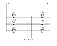
The six transistors and their anti -parallel diodes in the adjacent inverter circuit are numbered in the order of their leading start. A transistor is considered to be switched on if it runs himself or his diode.
The following 8 switching states are possible:
| Number | Turned on | Tame condition of the bridge branches |
|---|---|---|
| 0 | V2, v4, v6 | 000 |
| first | V1, v2, v3 | 110 |
| 2 | V2, v3, v4 | 010 |
| 3 | V3, v4, v5 | 011 |
| 4 | V4, v5, v6 | 001 |
| 5 | V5, v6, v1 | 101 |
| 6 | V6, v1, v2 | 100 |
| 7 | V1, v3, v5 | 111 |
States 1 to 6 form a symmetrical load -related star tension with the moment values + What / 3, +, + Ukai / 3, + U, 9, IOA / 3, / 3, 1 +UO/3, … etc. Your basic vibrations correspond to a three -phase system.
The conditions 0 and 7 switch the load without tension. They are used to reduce the output voltages on a short-term means. A sinus -shaped electricity is now reached by a time -weighted switchover between the 8 conditions.
To reduce switching processes and the associated switching losses, the conditions are
combined in their order. Let us assume that the voltage on the load should be changed in small steps with a reduced voltage from the switching state 1 (V1V2V3) to condition 2 (V2V3V4), i.e. H. the connected machine can be turned on 60 °-electrically. The switching sequence is available for this
- … V1V2V3, V1V3V5, V2V3V4, V2V4V6, V2V3V4, V1V3V5, V1V2V3… etc. at.
The individual lead times result from the tax algorithm used and from the height of the required parameter (voltage, electricity, torque).
With this order of the switching states, only one switching process takes place with every commutation. Usual PWM frequencies in the drive technology are between 2 kHz and approx. 20 kHz. With increasing switching frequency, the sinus is better approximated, the switching losses in the converter increase, the losses in the engine lose weight due to the better sinus -shaped current.
Optimization by overlapping upper vibrations [ Edit | Edit the source text ]
To further optimize the sinus commutation, the overlap of the third harmonic to the desired output frequency is used.

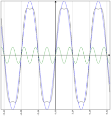
A normal sinus is shown in blue
f first ( x ) = 100 ⋅ sin ( x ) {displaystyle f_{1}(x)=100cdot sin(x)}. The factor 100 should symbolize a modulation with PWM from 0 to 100%.
The third harmonious one is shown in green


. The frequency is exactly 3 times as high and the phase position is the same as the basic vibration
f first ( x ) {displaystyle f_{1}(x)}
. The amplitude with a 15% pulse width was initially chosen arbitrarily. The curve shown in black now shows an addition of both sinus frequencies
f first ( x ) + f 2 ( x ) {displaystyle f_{1}(x)+f_{2}(x)}

. A resulting signal with a smaller amplitude is created, which is more similar to a rectangular signal than a sine curve. In addition, the maximum value of the amplitude is smaller than the originally undistorted sinus curve, because the 3rd harmonious frequency at the maximum value of the basic vibration always has its reverse maximum. If both sine vibrations are now generated in a microcontroller via a table, no computing power is required for addition and the pulse width modulator is only used to about 85% of its possible maximum work area. The remaining 15% can be used to increase the performance of the frequency converter.


Now, however, it is extremely problematic to operate different three -phase consumers (including asynchronous engines) with other forms of curve than with a sinus. Therefore, it is shown below that the commutation with the third harmonious has no influence on the sinus curve form at the output of the frequency converter.


- Blue is shown
L 1( x ) = 100 ⋅ sin ( x ) {Displaystyle l_ {1} (x) = 100cdot sin (x)} - Green is shown
L 2( x ) = 100 ⋅ sin ( x+2π3) {displaystyle L_{2}(x)=100cdot sin left(x+{frac {2pi }{3}}right)} - Is shown in red
L 3( x ) = 100 ⋅ sin ( x+4π3) {displaystyle L_{3}(x)=100cdot sin left(x+{frac {4pi }{3}}right)}


This results in the usual image of 3 three -phase. If a consumer is now connected between the phases instead of a star circuit (triangular circuit), the differential voltage between 2 phases results in a sinus -shaped voltage with an increased amplitude (yellow). So the difference of
L first ( x ) – L 2 ( x ) {Displaystyle l_ {1} (x) -L_ {2} (x)}A sinus -shaped result remains valid if too
L first ( x ) {displaystyle L_{1}(x)}

and
L 2 ( x ) {displaystyle L_{2}(x)}

the same function is added. With a shift of
2π3{displaystyle {tfrac {2pi }{3}}}
However, between the three -phases, the third upper vibration (orange shown) is completely identical to the next phase, since it is moved by exactly one full period. Therefore, when the commutation with the 3rd upper vibration at the output of the frequency converter, there is sinus -shaped tensions and currents regardless of whether the consumer is connected in star or triangle.


The increase in performance of the frequency converter and a drive connected to it is usually around 15%. This corresponds, for example, to the amplitude loss of a 6-pulse rotary current rectifier circuit, which delivers about 86% of the top voltage in the intermediate circuit.
Switching processes [ Edit | Edit the source text ]
Frequency converters work with steep switching flanks to minimize the power loss and achieve a high level of efficiency. In the case of IGBT frequency converters for 400 V network operation (560 V interim voltage), the IGBTs switch on within a few 100 NS. This leads to a high tension in the engine lines and in the engine. Even a capacity arms recommended by the manufacturer of the frequency converter, shielded engine line must not exceed a certain length (e.g. 20 m) due to its capacity covering and the reloading loss caused to the IGBT. In the case of longer engine lines, the peak streams do not grow further due to the wave resistance, but reflections and resonances, which, among others, occur. In addition to the additional burden already given, motor insulation.
If an engine line is not or not sufficiently connected to the inductance, the faults can subside into other circuit parts. The coupling mechanisms are capacitive, inductive or over earth grinding.
A suitable connection of the engine line is z. B. the large -scale edition of the shielding.
The electromagnetic compatibility can also be achieved or improved by mains and engine flow filters. Motor electricity filter (sinus filter) allow long supply lines and can also protect the engine from additional loads from the switching flanks and thereby increase the reliability.
Since some of the filter currents flow against mass, a TN S network system and/or a good local ground connection is necessary. Many frequency converters have increased dividing flows> 3.5 mA due to these filters and therefore require a fixed installation.
The product standard for frequency converters EN 61800-3 specifies limit values for interference.
Network resources [ Edit | Edit the source text ]
A simple frequency converter consists of an uncontrolled rectifier and a DC voltage circuit with electrolytic capacitors as an energy storage and to smooth the intermediate circuit voltage.
The network (voltage source with a low impedance) and the intermediate circuit (capacitors) are switched together with the help of the rectifier diodes. This leads to impulsive charging currents (low current flow angles) that load the network. Such frequency converters lead to a strong strain on the network and the intermediate circuit due to an increased effective current and it may reduce the lifespan of the frequency converter. These network resources can be mitigated by the prevalence of network throttles.
Frequency converters, which, without a intermediate circuit capacitor, also directly and change power-controlled power-controlled power-controlled power levers (matrix converters), avoid these high upper shaft currents. The highest performance withdrawal instead is much easier, i.e. H. Filter with small capacitors and throttles as the impulses for unpleasant napes. A slightly reduced maximum output voltage is disadvantageous, since no top value equal direction takes place.
Another variant is the proposal of a performance factor corrective filter level (PFC) for loading the intermediate circuit capacitor, which can also be recoverable. This allows operation that is largely free of mesh and avoids torque fluctuations due to interference between the network and output frequency.
Network reserves for frequency converters are specified in EN 61000-3. Details are hit for frequency converters up to a connecting performance (electricity equivalent) of 75 A per phase. Systems with larger connection services (> 75 a per phase) can significantly influence neighboring systems and possibly an entire low voltage network and are subjected to an individual assessment in accordance with current technical rules to the design of an individual assessment.
Specially optimized, double shielded and low -capacity cables are offered for the connection of the engine and converter. EMC screw connections are used to set up the umbrellas.
Since converter with a high voltage change speed d in /d t Working, the winding insulation of the engine is exposed to loads from partial loads (TE) compared to normal operation. For long lines (e.g.> 25 m) [2] Due to reflections and twisting processes, tension tips up to the double of the intermediate circuit voltage
( IN max ≈ 2 ⋅ IN ZK ≈ 2 , 8 ⋅ IN network z. B.: 2 , 8 ⋅ 400 IN = 1120 IN ) {displaystyle (U_{text{max}}approx 2cdot U_{text{ZK}}approx 2{,}8cdot U_{text{Netz}}quad {text{z. B.: }}2{,}8cdot 400,mathrm {V} =1120,mathrm {V} )}appear.


The isolation of the engine windings is thus experiencing a permanent stress that affects the lifespan. The tension on the winding changes so quickly that in the unfavorable cases (for parallel coil groups and wild winding), the isolation between two touching wires is used with the full peak tension.
In addition, capacities or unsuitable installation to the current flow between the motor shaft can lead to the grounded housing. This leads to electrical erosion in the camps and early wear. In addition to a selection of the motor (see DIN VDE 0530-25) suitable for converter operation, suitable precautions in the technical design and installation are taken. On the one hand, the interference level z. B. reduced by sinus filters and EMC-appropriate cabling or an electrically insulating coupling between the motor shaft and downforce prevents the current flow. [3]
In the case of systems to be converted, it may be necessary to renew the motor winding by a suitable voltage strength or an exchange of individual engines.
Since the PWM clock frequencies are often in the hearing area, disturbing noises often occur. The cause is capacitors, piezoelectric effects, magnetic forces or magnetostriction. To avoid such noises, the pulse frequency is increased to> 16 kHz if possible, which, however, increases the loss output of the frequency converter. This also worsens the EMC and the engine load increases. The pulse frequency can be adjusted from the audible area to> 16 kHz, especially for small converters.
Some frequency converters can cyclically change the PWM frequency by an average. This improves the subjective noise perception and the spectral distribution of the electrical disorders. The wobble of the pulse frequency has no influence on the operating behavior of the engine.
Instead of frequency converters, flow gears (turbore gaps) can be used. The performance transfer takes place here by a fluid. Turbore gaps are usually used where mechanical drives are already present and a regulation of the same is not possible. Flow gears are much more expensive than frequency converters and do not cause electromagnetic disorders. The efficiency is less than that of converters.
The classic alternative for large performance is a leonard set.
DC drives can be regulated by simpler chopping control, but have brush wear.
- Klaus bystron: Performance electronics of technical electronics. Volume 2, Carl Hanser, Munich/ Vienna 1979, ISBN 3-446-12131-5.
- Gert Hagmann: Performance electronics. 3. Edition. Aula-Verlag, Wiebelsheim 2006, ISBN 3-89104-700-2.
- Gregor D. HEARTLE, Heinz O. HEARTLE: Transformers and electrical machines in the energy technology systems. 2nd Edition. European teaching means, Haan-Gruit 1990, ISBN 3-8085-5002-3.
- Peter Friedrich Brosch: Modern stream judges. 5th edition. Vogel, Würzburg 2008, ISBN 978-3-8343-3109-0.
- Peter Friedrich Brosch: Practice of three -phase drives. Vogel, Würzburg 2002, ISBN 3-8023-1748-3.
- H. Greiner, H. Dorner: Cyclopedia -fed three -phase motors. Danfoss Bauer, Esslingen 04.2006, EP 2906. (PDF; 4.9 MB) Accessed on December 23, 2013 .
Standards [ Edit | Edit the source text ]
- DIN IEC 61800-3 (VDE 0160-103): 2012-09 Total-changing electrical drives. Part 3: EMC requirements including special test procedures
- DIN IEC 61800-5-1 (VDE 0160-105): 2008-04 Electrical power drive systems with adjustable speed. Part 5-1: Requirements for security-electrical, thermal and energetic requirements (IEC 61800-5-1: 2007)
- DIN EN 61000-3-2; VDE 0838-2: 2010-03: 2010-03 electromagnetic compatibility (EMC). Part 3-2: Limit values-limit values for upper vibration flows (device input current <= 16 A per ladder) (IEC 61000-3-2: 2005 + A1: 2008 + A2: 2009); German version EN 61000-3-2: 2006 + A1: 2009 + A2: 2009
- DIN EN 61000-3-12 (VDE 0838-12): 2012-06 electromagnetic compatibility (EMC). Part 3–12: Limit values-limit values for upper vibration flows, caused by devices and facilities with an input current> 16 a and <= 75 A per ladder that are provided for connection to public low-voltage networks (IEC 61000-3-12: 2011)
- DIN VDE 0530-17: 2007-12 rotating electrical machines. Part 17: Cycled-fed induction engines with cage runner-application guide (IEC/TS 60034-17: 2006; replacement for: DIN IEC/TS 60034-17 (VDE 0530-17): 2004-01)
- DIN VDE 0530-25: 2009-08 rotating electrical machines. Part 25: Guide for the draft and operating behavior of three-phase motors that are specially measured for converter operation (IEC/TS 60034-25: 2007); German version CLC/TS 60034-25: 2008 (replacement for: DIN CLC/TS 60034-25 VDE V 0530-25: 2006-01)
Recent Comments